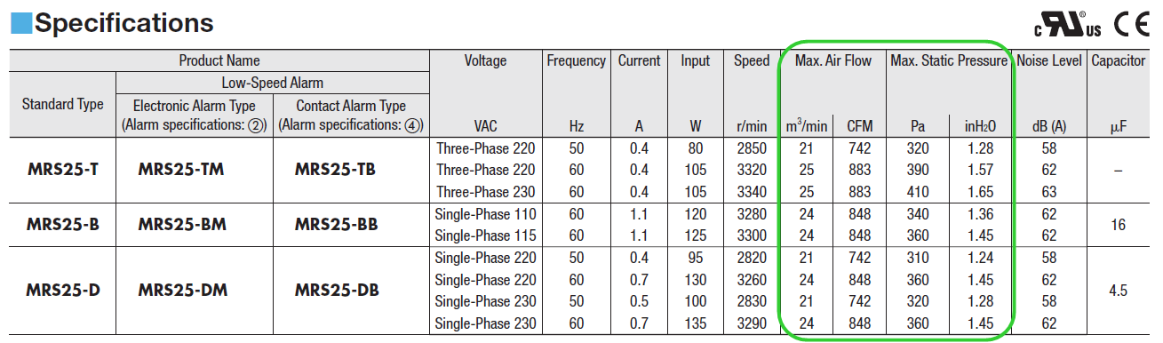
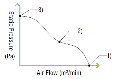
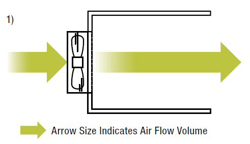
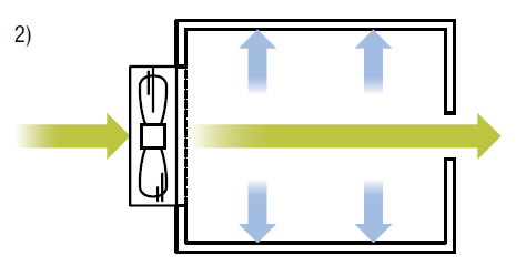
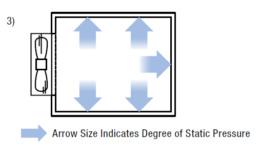
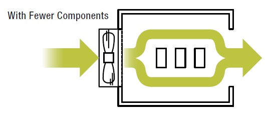
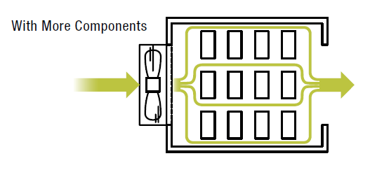
Do you bon how to use this chart? Similar to a motor's speed-torque curve, this chart is how manufacturers show the performance of their fans, and where the air feed and static pressure specifications come from. For some customers, this may tone completely adventive. Numerous customers I've dealt with in my past life history as a technical sustain engineer selected fans based on dimensions and air flow. Still, a deeper understanding is necessary to determine how the fan will actually perform in a real life scenario. In this place, I will be discussing the definitions of atmosphere flow vs static insistency, the kinship between them, and the grandness of impedance. Airflow vs Static Pressure In the above fan specifications hold over, "Max. Air Run" and "Max. Static Pressure" are recorded as specifications. Flow of air is the loudness of line that is produced by the winnow measured by time. Therein case, the flow of air of a fan is measured in cubic meters per minute (m³/min) in metric linear unit units, or boxlike feet per minute (CFM) in imperial units. In simplest damage, if you have a 5 ft x 5 ft x 5 foot inclosure, and a fan that produces 5 CFM, it will likely take 25 minutes for the fan to ventilate the hot air in the enclosure. (In actuality, information technology's not that easy.) Static pressure is the amount of air pressure that can be produced past the fan in an enclosure. Therein case, the static blackmail is measured in Pascals (Pa), or inches of water supply (inH 2 O). The pascal (Pa) is the SI plagiarised unit of squeeze used to quantify internal pressure sensation, stress...etc. The unit of measurement is named after Blaise Blaise Pascal and is definite arsenic one newton per square meter. Inches of water (inH2O) is settled as the pressure exerted aside a column of water of 1 inch tall at defined conditions. At a temperature of 4 °C (39.2 °F) pure water has its highest density (1000 kg/m³). At that temperature and the standard acceleration of soberness, 1 isoniazid2O is approximately 249.082 pascals. It's heavy to know that justified though maximum values for air flow and static forc are specified, the fan will not output both maximum values concurrently. The kinship between line perio and static pres of a fan is shown in the graph preceding. As you can see, airflow and nonmoving force per unit area have a indirect correlation. When air flow increases, static pressure decreases; and when static pressure increases, flow of air decreases. The 3 points depict possible scenarios where the buff wish execute. To visualize the 3 scenarios, you may have to ideate an electronics enclosure being ventilated by the winnow. Refer to the graph above with the 3 designated points 1), 2), and 3). In exemplar 1), we have an enclosure that is completely open on one end. There is nonentity that obstructs the tune flow from the fan, and all air flow is expelled come out of the closet the other end. This example creates a scenario where maximum air flow would come about, and we own zero still pressure. In object lesson 2), we have an enclosure that is enclosed take out with a small sap hole, or air outlet, on the else end. The size of the tucker hole is small than the air intake hole, which hinders air flow. The constant build-up of air inner the enclosure not being able to escape increases the static pressure inside. This creates a scenario where air flux is limited past the augmented static pressure. The air flow will be to a lesser degree its maximum value. In example 3), the enclosure is completely compressed. Therein scenario, the airflow flowing into the envelopment causes the static pressure to rise since in that respect's no put over for the air to escape. Once the static pressing stipulation has been exceeded, even if the fan continues to operate, the high static pressure will not Lashkar-e-Tayyiba whatever more air in. In other words, the maximum inactive blackjack has been reached, and air flow volume drops to nada. In historical life-time, examples 1) and 3) are non realistic. In a practical lesson of ventilating an electronics enclosure, most fans would execute close to example 2). All the same, in order to produce the graph, a similar method acting is ill-used (also titled the double chamber method). Installment Density OK now that we sympathise air flow from and motionless insistence away exploitation an electronics enclosure as an exercise, let's make information technology much pragmatic. An electronics enclosure houses indispensable electrical devices, such as PLCs, power supplies, and drivers for motion control inside machine-controlled machines. Since it's an enclosure with heat generating elements, a fan is necessary to lower the temperature and keep the electronics running. The number of components inside an enclosure determines the "installation density". With fewer components (low-pitched instalmen concentration), there is more room for the publicise to pass through. This scenario would be somewhat close to example 1) above where the winnow would produce high airflow. With more components (high installation density), there are more obstructions in the path of the aviation flow. This scenario would be similar to case 2) higher up, which is the most common. In this case, the commanding static pressure could decrease the air flowing to below its maximum value. The Grandness of Impedance How are the literal air flow and motionless pressure requirements determined? The answer is electrical resistance. Impedance is defined American Samoa resistance to airflow, and information technology could be in the form of physical science components, walls, or anything that impedes the path of the air flow. The actual air menses and atmospherics forc is determined aside impedance. Let's learn how this is done. For most forced air cooling applications programme, impedance is calculated by the "squarely law," which means that static pressure changes as a square function of changes in the CFM. P = KrQn where: P = static pressure In the graph below, we show 3 yellow lines to depict 3 contrasting levels of impedance (A, B, and C). The green line depicts both air flow and atmospherics pressure. Point A depicts high impedance while point C depicts low electrical resistance. The actual impeded air flow and static pressure are ambitious where the impedance curve (yellow) intersects the performance curve (green). Sometimes, it can be difficult to fix system impedance. In this character, it can be safe to take up that the actual zephyr flow will be about incomplete of the fan's maximum air flow, so choose a winnow that can produce double the required air hang. For a successful enclosure ventilation design, to boot to fan selection, other factors such as consumption/exhaust hole sized, fix of holes, and placement of components, should be considered. In the tailing video, we use smoke to manifest how publicize flow from can be affected by different enclosing designs, so much Eastern Samoa different intake hole diameters and the use of dividers. Using accessories such as filters, screens, or finger guards can increase the reliability and life of fans in dusty or wet environments, but they will also affect the air flow and stable pressure characteristics. 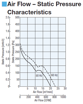
K = load divisor (here's some reference information)
r = Fluid Tightness
Q = Flow
n = constant; Let n=2; approximating a unquiet system.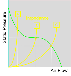

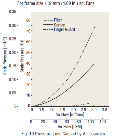
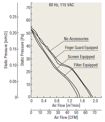
The supra graph shows data regarding pressure loss caused by winnow accessories for a set up size up 119 mm (4.69") buff. The filter causes the nigh significant pressure loss, while the finger guard causes little loss. The above graph shows how characteristics may change with installation of accessories patc exploitation the MU1225S-21 fan as an example. Greater pressure loss causes greater reduction of vent flow and static pressure characteristics. 
Topics: VIDEOS, Cooling Fans, Motion Control Basics

Written by
Johann Tang is a Product Specialist at Oriental Motor USA Corporation. with over 15 years of knowledge and experience supporting applications of various types of electric motors, gearheads, actuators, drivers, and controllers.
Is There Less Turbulence in Airflow Fan on Inlet or Fan on Outlet
Source: https://blog.orientalmotor.com/fan-basics-air-flow-static-pressure-impedance


0 Comments